3d Printer Part 2
I had not grounded pin 1 on the 555 is why it wasn't working. The following gif is a simulation of what it looks like working:

I took a picture of it on and one of it off and since I had to touch the camera the image moved. I edited the rest of the image out with an opaque mask but didn't align the two images positionally. That's why the gif looks like universe warps around the lit led. The real circuit is flashing about twice as fast as it is simulated here. The rate can be changed by fiddling with the resisters and/or capacitor. The is a formula one can use to maintain tight control but I don't need it for what I'm doing. I wish I owned an oscilloscope- then I could be one of the cool kids.
I'm powering this stuff with an atx power supply. Red wires have 5v+. Ground out the green one and the power supply gets turned on- oo la la!
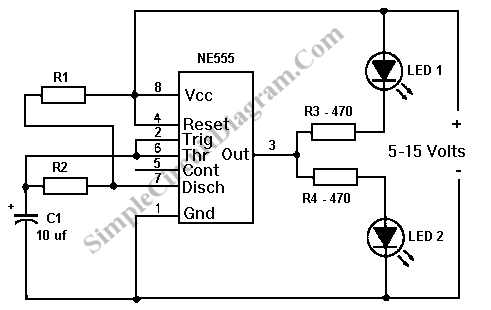
This is the circuit I'm using minus the led connected to vcc.

Notes to self:
A+ = Black
Acom = Red
A- = Brown
B+ = Yellow
Bcom = Blue
B- = Orange
https://learn.adafruit.com/downloads...per-motors.pdf


I took a picture of it on and one of it off and since I had to touch the camera the image moved. I edited the rest of the image out with an opaque mask but didn't align the two images positionally. That's why the gif looks like universe warps around the lit led. The real circuit is flashing about twice as fast as it is simulated here. The rate can be changed by fiddling with the resisters and/or capacitor. The is a formula one can use to maintain tight control but I don't need it for what I'm doing. I wish I owned an oscilloscope- then I could be one of the cool kids.
I'm powering this stuff with an atx power supply. Red wires have 5v+. Ground out the green one and the power supply gets turned on- oo la la!
This is the circuit I'm using minus the led connected to vcc.

Notes to self:
A+ = Black
Acom = Red
A- = Brown
B+ = Yellow
Bcom = Blue
B- = Orange
https://learn.adafruit.com/downloads...per-motors.pdf


Comments
Post a Comment