555 Module and Soundcard Oscilliscope
As I'm still waiting on parts, I decided I needed a 555 circuit module
because I build the circuit so often. If I had the circuit ready to go, I
could just plug it in without worrying about messing with that part and
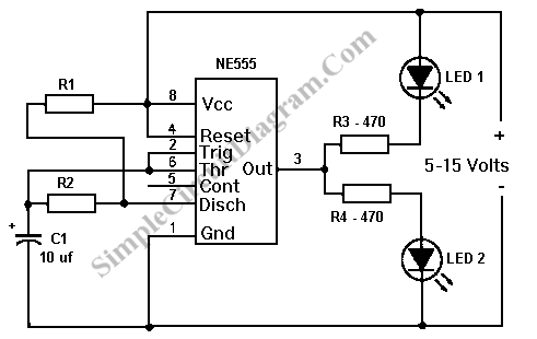
get to the nitty gritty. The 555 circuit I have built a zillion times
looks like this:

Or like this depending on your perspective:

Any ways looking for resisters and hooking all that crap up every time I need it gets old so I needed a ready made reusable dealie I could just plug in.
However, since I'm not too interested in doing all the math, I wanted to work everything out without thinking about it. So I made the sound card oscilloscope so I could measure the frequencies and see the waveform right on my computer like so:

That picture is an actual capture of my computer reading the 555. The circuit for the probe looks like this:

And I didn't photograph the actual probe circuit because it doesn't look impressive and this kid would pop out and heckle me:

Anywho! I managed to do all the horrid planning and soldering to get all the components(6 resisters, 3 switches, an LED, a capacitor, an IC, and the 3 pin header) I needed in a 1 inch square and tested it with my new $3 oscilloscope. It look like this:


The switches change the frequency between these:
~2 hertz
~20 Hertz
~110 hertz
~160 hertz
That's plenty of variation for experimentation.

Or like this depending on your perspective:

Any ways looking for resisters and hooking all that crap up every time I need it gets old so I needed a ready made reusable dealie I could just plug in.
However, since I'm not too interested in doing all the math, I wanted to work everything out without thinking about it. So I made the sound card oscilloscope so I could measure the frequencies and see the waveform right on my computer like so:

That picture is an actual capture of my computer reading the 555. The circuit for the probe looks like this:

And I didn't photograph the actual probe circuit because it doesn't look impressive and this kid would pop out and heckle me:

Anywho! I managed to do all the horrid planning and soldering to get all the components(6 resisters, 3 switches, an LED, a capacitor, an IC, and the 3 pin header) I needed in a 1 inch square and tested it with my new $3 oscilloscope. It look like this:


The switches change the frequency between these:
~2 hertz
~20 Hertz
~110 hertz
~160 hertz
That's plenty of variation for experimentation.


Comments
Post a Comment